
Electric current is the rate of charge flow past a given point in an electric circuit, measured in Coulombs/second which is named Amperes. In most DC electric circuits, it can be assumed that the resistance to current flow is a constant so that the current in the circuit is related to voltage and resistance by Ohm’s law. The standard abbreviations for the units are 1 A = 1C/s.
Simple Electric Circuits
Simple Circuit Components
Identify simple circuit components
An
electric circuit contains a source of moving charge (battery or
generator), connecting wires made of conducting materials (usually
copper metal) and various electrical devices such as bulbs, switches,
resistors, ammeters and voltmeters.
electric circuit contains a source of moving charge (battery or
generator), connecting wires made of conducting materials (usually
copper metal) and various electrical devices such as bulbs, switches,
resistors, ammeters and voltmeters.
Voltmeters
measure potential difference in volts. While resisters opposes the flow
of current. The circuit may also contain devices for controlling the
amount of current. These include:
measure potential difference in volts. While resisters opposes the flow
of current. The circuit may also contain devices for controlling the
amount of current. These include:
- Rheostat
- Fuse
- Circuit breakers, as well as devices for measuring current such as ammeters and galvanometers.
The table below shows list of some common circuit component and their purpose.
| Circuit device | Purpose |
| Connecting wire | Carry current from point to point in a circuit. |
| Wire joined | |
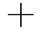
| Wire crossing (can be connected) | |
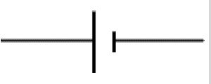
| Cell | Supplies electrical energy |
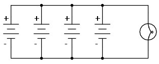
| Battery (4 cells) | Supplies electrical energy |
| Battery (multiple cells) | |
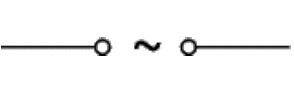
| Alternating current (AC) supply | |
| Lamp/bulb | Supplies electrical energy |
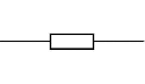
| Resistor | Impedes the flow of current |
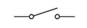
| Switch | Open and closes a circuit |
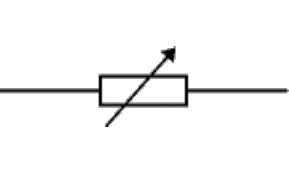
| Rheostats (variable resistors | Control amount of current. For example the brightness of a lamp) |
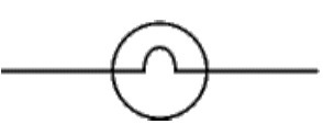
| Galvanometer | Detecting the presence of current |
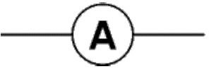
| Ammeter | Measures current |
| Milliammeter | |
| Voltmeter | Measures potential Difference (voltage) |
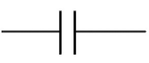
| Capacitor | Store charges |
Simple Electric Symbols
Identify simple electric symbols
Connecting wire
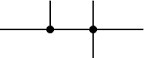
Wire joined
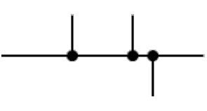
Wires crossing
Cell
Battery
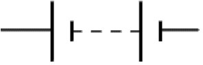
Battery (multiple cells)
Alternating current (AC) supply
Lamp/bulb
Resistor
Switch
Rheostats (variable resistors)
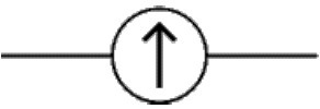
Galvanometer
Ammeter
Milliammeter

Voltmeter

Capacitor
Potential Difference (P.D)
Potential difference or voltage is a measure of electrical energy.
Potential
difference (p.d) between the +ve and –ve terminals of a battery causes a
current to flow along any conducting path that links them.
difference (p.d) between the +ve and –ve terminals of a battery causes a
current to flow along any conducting path that links them.
The Concept of Current, Voltage and Resistance
Explain the concept of Current, Voltage and Resistance
CURRENT
An
electric current in a material is the passage of charge through the
material. In metals free electrons carry charge. In solutions such as
sodium chloride it is carried by charged particles known as ions.
electric current in a material is the passage of charge through the
material. In metals free electrons carry charge. In solutions such as
sodium chloride it is carried by charged particles known as ions.
Insulators
like wood and plastic do not contain charge carriers at all as every
electron is firmly fixed onto their atoms. The electrons are not free to
move.
like wood and plastic do not contain charge carriers at all as every
electron is firmly fixed onto their atoms. The electrons are not free to
move.
The
rate of flow of electrons in a material is called electric current. It
is measured in amperes (A) using an Ammeter. Connection can damage them.
Therefore when connecting the ammeter, the red wire should be connected
to the +ve terminal of a battery.
rate of flow of electrons in a material is called electric current. It
is measured in amperes (A) using an Ammeter. Connection can damage them.
Therefore when connecting the ammeter, the red wire should be connected
to the +ve terminal of a battery.
A current of 1A is equivalent to a flow of6.25 x 1018electrons per second and 1 electron has a charge of 1.6x 10⁻¹⁹c.
Current in simple circuit is the same at all points.
Once
the circuit is complete, electric charges inside cells and other
sources of electric charge are forced out into the circuit.
the circuit is complete, electric charges inside cells and other
sources of electric charge are forced out into the circuit.
The
electric energy is normally given out as light and heat, as energy goes
through the bulb. A car headlamp has about 4A of current passing
through it while a small torch uses about 0.2A.
electric energy is normally given out as light and heat, as energy goes
through the bulb. A car headlamp has about 4A of current passing
through it while a small torch uses about 0.2A.
VOLTAGE
When
several cells have been joined together, they form a battery. Every
cell has a voltage, commonly referred to as potential difference (p.d).
This potential difference (p.d) causes the flow of electrons (charges)
in a circuit.E.g. A dry cell has a voltage of 1.5v. This voltage is
normally marked on the cell.
Voltage
is measured by using a voltmeter. The SI unit for voltage is the volt
(V). If each coulomb if charge is given 1 joule of potential energy,
then the p.d across the terminals of a battery is 1 volt.
is measured by using a voltmeter. The SI unit for voltage is the volt
(V). If each coulomb if charge is given 1 joule of potential energy,
then the p.d across the terminals of a battery is 1 volt.
The p.d between the ends of a connecting wire is zero since there is almost no loss of potential energy over this section.
P.d
across the battery = sum of p.d around a conducting path, whereas
voltage provides the driving force to an electric current, this force is
always opposed.
across the battery = sum of p.d around a conducting path, whereas
voltage provides the driving force to an electric current, this force is
always opposed.
RESISTANCE
Is
the opposition flow to an electric current. As current flows through
the circuit it encounters some opposing force. This force determines the
amount of current flowing in an electric device.
the opposition flow to an electric current. As current flows through
the circuit it encounters some opposing force. This force determines the
amount of current flowing in an electric device.
The
property of conductors that oppose the flow of electric charges depends
on the relationship between current and voltage across their ends as
discovered by George Ohm. He observed that voltage across a conductor
was directly proportional to electric current flowing through it
provided that temperature and other physical conditions of the conductor
were kept constant.
Hence, V x I
V= IR
R is the constant of proportionality. This constant is called resistance and the above relationship is known as Ohms law.
Resistant (R) = p.d across the conductor/Current through the conductor
Therefore a resistance of 1ohm is obtained when a p.d of 11V cause a current of 1A to flow in a circuit.
| name | symbol | conversion | example |
| milli-ohm | mΩ | 1mΩ = 10-3Ω | R0 = 10mΩ |
| ohm | Ω | – | R1 = 10Ω |
| kilo-ohm | kΩ | 1kΩ = 103Ω | R2 = 2kΩ |
| mega-ohm | MΩ | 1MΩ = 106Ω | R3 = 5MΩ |
A resistor
Is
a device especially designed to offer resistance to the flow of an
electric current, Resistors include rheostats (variable resistor) and
fixed resistors.
a device especially designed to offer resistance to the flow of an
electric current, Resistors include rheostats (variable resistor) and
fixed resistors.
Ohm’s Law
Ohms
law states, “At constant temperature and other physical factors, the
potential difference across the end is directly proportional to the
current passing through a conductor (wire).”
law states, “At constant temperature and other physical factors, the
potential difference across the end is directly proportional to the
current passing through a conductor (wire).”
A graphical representation of Ohm’s law. The graph of voltage against current
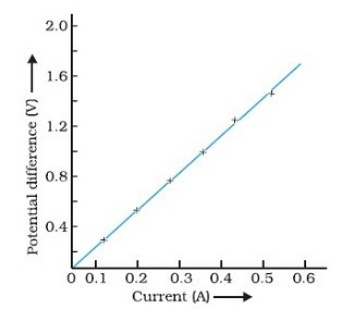
The
gradient of the particular graph represents resistance. This is
constant for a particular wire or conductors. Doubling the voltage would
double the current; a graph of this kind passes through the origin.
gradient of the particular graph represents resistance. This is
constant for a particular wire or conductors. Doubling the voltage would
double the current; a graph of this kind passes through the origin.
FACTORS THAT AFFECT THE RESISTANCE OF A CONDUCTOR
The resistance of a conductor is affected by the following factors:
Length of the conductor
The
longer the wire, the higher the resistance, short lengths of wire
produce resistors of low resistance while long lengths of the same wire
are good for high – value resistance.
longer the wire, the higher the resistance, short lengths of wire
produce resistors of low resistance while long lengths of the same wire
are good for high – value resistance.
Temperature
An
increase in temperature of a conductor means an increase in its
resistance and vice versa. This is important in resistance thermometers.
The resistance of metal conductor increases with increase in
temperature.
increase in temperature of a conductor means an increase in its
resistance and vice versa. This is important in resistance thermometers.
The resistance of metal conductor increases with increase in
temperature.
Types of material
The
conducting ability of the material has to be considered. A chrome wire
has more resistance than a copper wire of the same dimension. That is
why copper is mostly used for connecting wire.
conducting ability of the material has to be considered. A chrome wire
has more resistance than a copper wire of the same dimension. That is
why copper is mostly used for connecting wire.
Cross – sectional area
A
thin wire has more resistance than a thick conductor. The filament of a
bulb is made of very thin tang stem wire. It therefore has a high
melting point.
thin wire has more resistance than a thick conductor. The filament of a
bulb is made of very thin tang stem wire. It therefore has a high
melting point.
With
all other factors being equal, a long wire has more resistance than a
short wire and thin wire has more resistance than a thick one. Therefore
resistance of a conductor varies depending on the current flow.
all other factors being equal, a long wire has more resistance than a
short wire and thin wire has more resistance than a thick one. Therefore
resistance of a conductor varies depending on the current flow.
The SI Units of Current, Voltage and Resistance
State the SI units of Current, Voltage and Resistance
Current
The
rate of flow of electrons in a material is called electric current. It
is measured in amperes (A) using an Ammeter. The SI unit for current is
ampere.
rate of flow of electrons in a material is called electric current. It
is measured in amperes (A) using an Ammeter. The SI unit for current is
ampere.
Voltage
Voltage is measured by using a voltmeter. The SI unit for voltage is the volt (V)
Resistance
Resistant (R) = p.d across the conductor/Current through the conductor. The SI unit for resistance is Ohm.
Connecting Simple Electric Circuits
Connect simple electric circuits
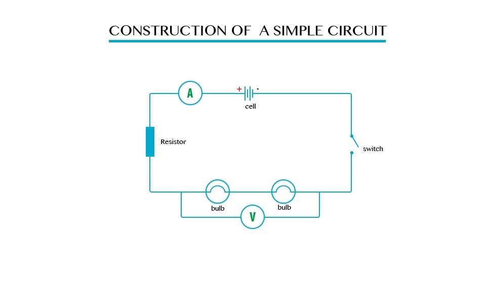
CONSTRUCTION OF SIMPLE ELECTRIC CIRCUITS
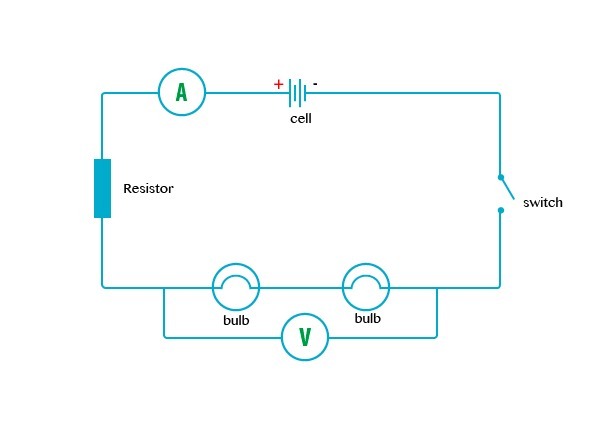
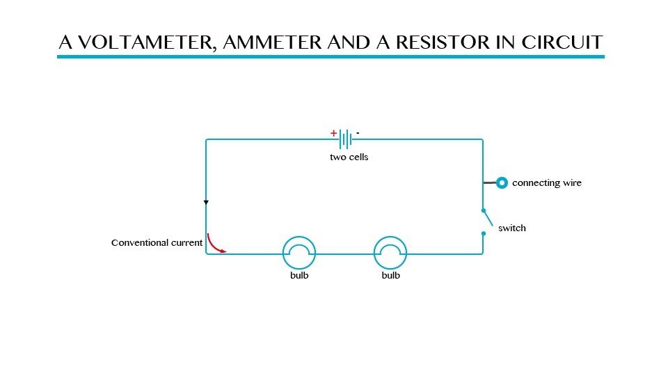
Consider a circuit consisting of a battery, a switch and 2 bulbs.
When
the switch is closed, current flows through the wires and the bulbs
light up. The circuit is said to be complete. When the switch is opened,
no current flows through the wire, as the path carrying current is
broken. The circuit is said to be incomplete.
the switch is closed, current flows through the wires and the bulbs
light up. The circuit is said to be complete. When the switch is opened,
no current flows through the wire, as the path carrying current is
broken. The circuit is said to be incomplete.
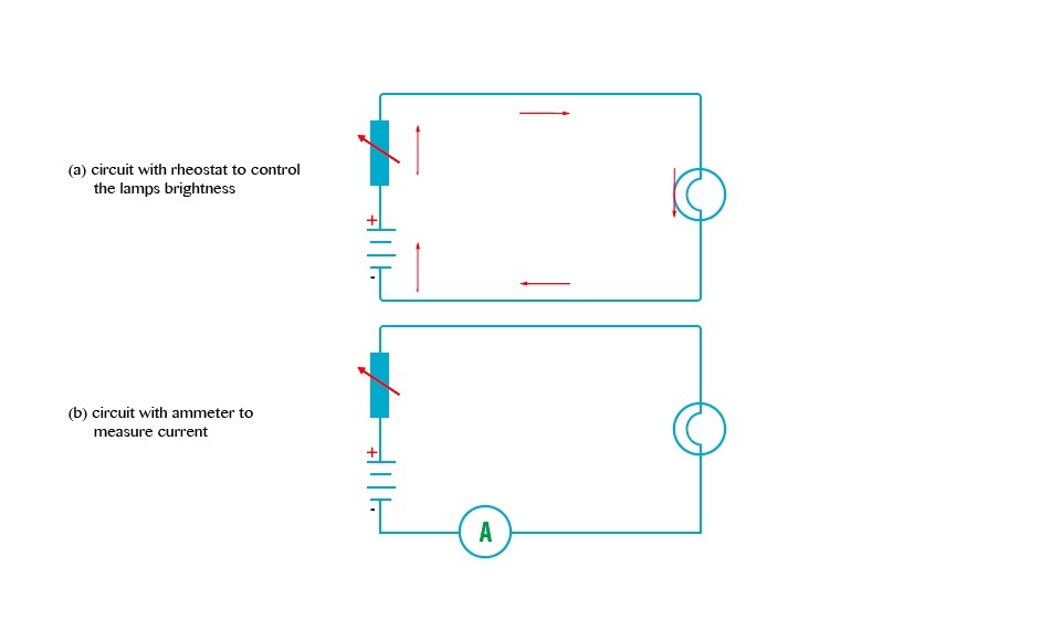
If we want to be able to control the brightness of the lamp, we include a rheostat into the circuit.
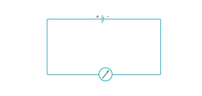
In
a circuit an ammeter is always connected in series with the battery.
Current has to pass through the ammeter if it is to be measured
correctly.
a circuit an ammeter is always connected in series with the battery.
Current has to pass through the ammeter if it is to be measured
correctly.
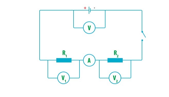
Unlike
an ammeter, a voltmeter must be connected in parallel with component so
as to measure the voltage drop across it. The figures show a simple
electric circuit in which the ammeter and voltmeter are connected in
series and parallel respectively.
an ammeter, a voltmeter must be connected in parallel with component so
as to measure the voltage drop across it. The figures show a simple
electric circuit in which the ammeter and voltmeter are connected in
series and parallel respectively.
As
already learnt, resistance is the ratio of the potential difference
across the ends of the conductor,a very good conductor will have 0
resistance.
already learnt, resistance is the ratio of the potential difference
across the ends of the conductor,a very good conductor will have 0
resistance.
Resistance of resistor R could be calculated using the formula:- R = V/I
R = V/I
Not that the rheostat (variable resistor) moves, it varies with the length of the conductor being used.
Example 1
A battery of 5V has a resistance wire of 20Ω connected to it. Calculate the current in the circuit.
Solution;
I = V/R = 5V/20Ω
I = 0.25A
Therefore,
Current in the circuit = 0.25A
Example 2
Calculate the reading of the Voltmeter P and the ammeter Q in the electric circuit below.
Solution:
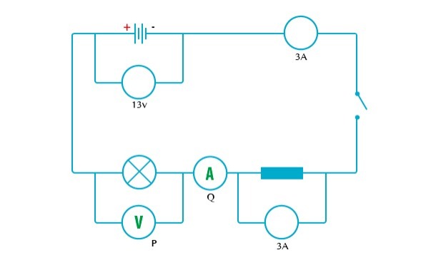
Being a single loop circuit, current is the same at all points.
Q = 3A
Sum of p.d in external circuit = p.d across battery
3V + P = 13V
P = 10V
Therefore:
Q = 3A and Voltmeter P = 10V
Note: for a single loop or simple circuit.
- Current is the same at all points around the circuit
- The
sum of the potential differences around a conducting path from one
battery terminal to the other terminal within the circuit is the same as
the p.d across the battery.
Electric Current and Voltage
Measure electric current and voltage
MEASUREMENT OF ELECTRIC CURRENT
Since we cannot see electric current to measure it, we must observe some of its visible effects, like deflection of pointers.
Beside
an ammeter, an electric current is measured using Milliammeter and
microammeters. These devices are normally connected in series with the
source of current e.g. circuit with a galvanometer connected in series.
an ammeter, an electric current is measured using Milliammeter and
microammeters. These devices are normally connected in series with the
source of current e.g. circuit with a galvanometer connected in series.
Galvanometer in series
Galvanometer
can only measure very small current of a few hundred microamperes. To
measure large currents a resistor is added to make current flow through
it and a very small amount of current flows to the galvanometer. This
combination is called an ammeter.
can only measure very small current of a few hundred microamperes. To
measure large currents a resistor is added to make current flow through
it and a very small amount of current flows to the galvanometer. This
combination is called an ammeter.
On
the other hand voltage is measured depending on the amount of current
passing through the circuit. In Ohmic device it is given as V^I.
the other hand voltage is measured depending on the amount of current
passing through the circuit. In Ohmic device it is given as V^I.
Simple Electric Circuits
Analyse simple electric circuits
Combination of resistors
There
are two main methods of connecting circuit components, in series or in
parallel. Resistors can be connected either in series or in parallel
depending on the desired output.
are two main methods of connecting circuit components, in series or in
parallel. Resistors can be connected either in series or in parallel
depending on the desired output.
Series combination
In series arrangement the resistors are connected end to end.
In a simple circuit
V = V1 + V2 or V- (V1 + v2)= 0
This means that the sum of the p.d across the resistors is the same as the p.d across the battery.
Current is the same at all points around the circuit.
Resistors connected in series
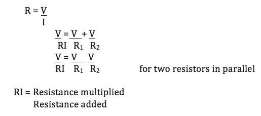
Parallel combination
Resistors are connected across two common points in a parallel arrangement.
Note;
Potential difference is from a single source and so is the same for all
the branches. However the current is different in each branch.
Potential difference is from a single source and so is the same for all
the branches. However the current is different in each branch.
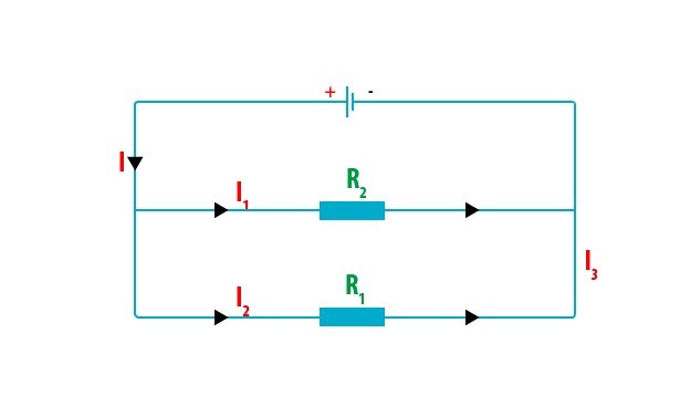
From Ohm’s law;
Note:
When
bulbs have to be powered by a single source of electric current, the
bulbs are connected in parallel. This is practiced in car and home
lighting system.
bulbs have to be powered by a single source of electric current, the
bulbs are connected in parallel. This is practiced in car and home
lighting system.
The advantage of parallel arrangement over series arrangement is that:
- The full p.d of source is applied across each bulb irrespective of the number of bulbs.
- Switching one bulb on and off does not affect the others.
Example 3
consider the figure below:
Given that the p.d a cross the cell is 24V, calculate the p.d across the 4Ω and 6Ω.
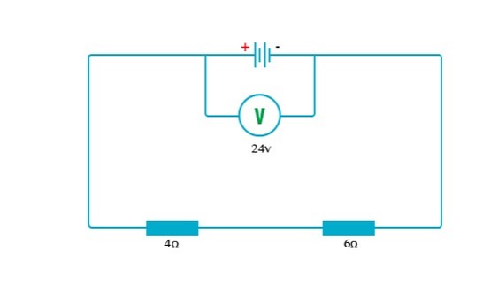
Solution;
Total resistance in the circuit = 4Ω + 6Ω= 10Ω
Using Ohm’s law. I = V/R,
Current in the circuit = 24V/10Ω= 2.4A
This implies the 2.4A passed through the 4Ω resistor.
The pd across it can be obtained through V=IR
p.d = 2.4A x 4N = 9.6V
Note that the p.d across two resistors adds up to the battery p.d.
p.d across the 6Ω = (24-9.6) V
= 14.4V
Therefore,
P.d across the 6Ω =14.4V

