Light is a form of energy which controls the sense of vision.
Difference between Concave and Convex Mirrors
Distinguish between concave and convex mirrors
Concave mirror is a spherical mirror whose reflecting surface is curved inwards. A Good example is the driving mirror of a car.
Convex mirror is a spherical mirror whose reflective surface is curved outwards. A good example of a convex mirror is a shaving mirror.
General demonstrations of convex and concave mirrors (curved mirrors:
The Terms Principle, Axis, Pole, Principle Focus and Radius of Curvature as Applied to Curved Mirrors
Explain the terms principle, axis, pole, principle focus and radius of curvature as applied to curved mirrors
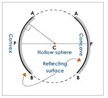
Terms used in studying curved mirrors
- Centre of curvature (C):the centre of the sphere of which a mirror is a part of.
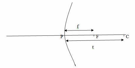
- Radius of curvature (R): the radius of sphere of which a mirror is a part of.
- Pole (P): the central point of the reflecting surface of spherical mirror (curved or convex mirror).
- Principal axis:the straight line joining the centre of curvature (C) and the pole (P).
- Principal focus (F):the point o the principal axis where light rays tend to intersect. This point is between centre of curvature and the pole.
- Principal axis:the straight line joining the centre of curvature (C) and the pole (P).
- Principal focus (F):the point on the principal axis where light rays tend to intersect. This point is between centre of curvature and the pole.
The Images Formed by a Curved Mirror
Locate the images formed by a curved mirror
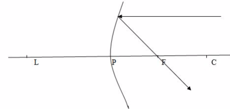
Case (1)
When
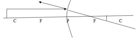
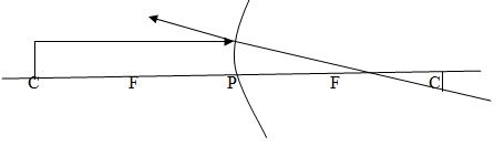
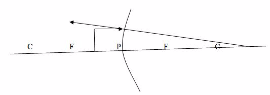
a beam of light parallel and very close to the principal axis, CL, is
reflected from a concave mirror, it converges to a point, F, on the
principal axis called the principal focus.
a beam of light parallel and very close to the principal axis, CL, is
reflected from a concave mirror, it converges to a point, F, on the
principal axis called the principal focus.
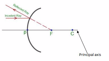
Case 2
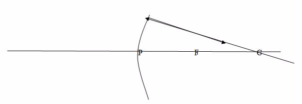
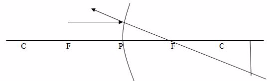
When a ray passes through the principal focus, F, it is reflected parallel to the principal axis.
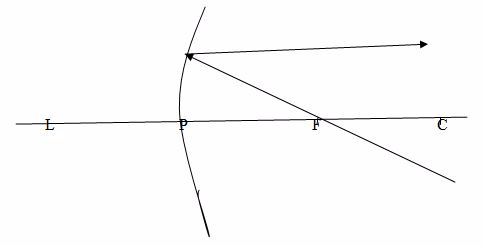
Case 3
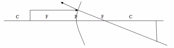
When
a ray passes through the centre of curvature, C, which therefore
strikes the mirror at normal incidence, it is reflected back along its
original path.
a ray passes through the centre of curvature, C, which therefore
strikes the mirror at normal incidence, it is reflected back along its
original path.
Note: Concave mirrors have a real focus because light passes through the focus.
The formation of images by concave mirror tends to change as the position of object changes.
Case 1: Image (I) formed by a concave mirror when the object is beyond C.
Properties of images formed:
- The image is between C and F
- The image is smaller than the object
- The image is inverted (upside down)
- The image is real
Case 2: The object is placed at C
Properties of image
- The image is formed at C
- The image has the same size as object
- The image is inverted (upside down)
- The image is real.
Case 3: The object is placed between C and F
Properties of image formed
- The image is real
- The image is large than object
- The image is formed beyond C
- The image is inverted (upside down)
- The image is real
- The image is large than object
- The image is formed beyond
- The image is inverted (upside down)
Case 4:The object is placed at F
Properties of image:
- The image is formed at infinity (x)
- The image is formed beyond C
- The image is large than object
- The image is Real
Case 5:The object is placed between F and P.
Properties of image formed:
- The image is virtual
- The images is upright
- The image is formed behind the mirror
- The image is large than the object
Formation of images in a convex mirror:
Obviously,there isonly one kind of image formed when an object is placed at any position.
Properties of image formed by convex mirror:
- the image is virtual
- the image is upright
- The image is smaller than object (diminished)
- The image is formed behind the mirror.
Example 1
An
object 2cm long is erected 8cm infront of a concave mirror of radius of
curvature 10cm. By using a scale drawing, determine the position, size
and nature of image formed.
object 2cm long is erected 8cm infront of a concave mirror of radius of
curvature 10cm. By using a scale drawing, determine the position, size
and nature of image formed.
Data given
- Height of object, Ho = 2cm
- Object distance, U= 8cm
- Radius of curvature, r = 10cm
- Focal length,f =8cm
- Choose suitable scale.
- Say 1cm represents 5cm
From this scale then
- Height of object, Ho = 2cm
- Object distance, U= 2cm
- Focal length, F = 2.5cm
Thus,
Image distance, V = X
Image Height, H1=Y
The Focal Length of a Concave Mirror
Determine practically the focal length of a concave mirror
Focal length (f) is the distance between the principal focus and the pole.
Convex and Concave Mirrors in Daily Life
Use Convex and concave mirrors in daily life
Curved mirrors are used as:
- Driving mirrors
- Shaving mirrors
- Reflectors
Question Time 1
Why is convex mirror used as driving mirror?
The convex mirror is used as driving mirror because it provides the wider field of view.
Question Time 2
Why concave mirror used as shaving mirror?
Concave mirrors are used as shaving mirrors because they form an enlarged image when held close up.
Refraction of Light
The Concept of Refraction of Light
Explain the concept of refraction of light
Refraction
of light refers tothe bending of light as it passes through two
different medium because the speed of light tends to change when
travelling from one medium to another.
of light refers tothe bending of light as it passes through two
different medium because the speed of light tends to change when
travelling from one medium to another.
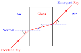
Figure showing refraction of light as it passes from air to glass.
The Angle of Incidence and Angle of Refraction
Measure the angle of incidence and angle of refraction
The angle of incidence (i)is the angle between the incident ray of light and the normal at the point of incidence.
The angle of Refraction (r)is the angle between the refracted ray and the normal at the point of incidence.
The Laws of Refraction
State the laws of refraction
First law of refraction
The
First Law of refraction states that “the incident ray, the refracted
ray and the normal at the point of incident are located in the same
plane.”
First Law of refraction states that “the incident ray, the refracted
ray and the normal at the point of incident are located in the same
plane.”
Second law of refraction
Second
Law of refraction states that “when a light ray passes from one medium
into another medium, the angle of incidence (i) and corresponding angle
of refraction( r) are such that the ratio of sine of the angle of
incidence to the sine of the angle of refraction (sini/sinr) is a
constant value called the refractive index.”
Note:
The Second Law of Refraction is called Snell’s Law in honour of a Dutch
scientist named Snell (1591 – 1626) who first described it.
The Second Law of Refraction is called Snell’s Law in honour of a Dutch
scientist named Snell (1591 – 1626) who first described it.
The Refraction Index of a Material
Determine the refraction index of a material
Refractive index (n) is the ratio of the sine of the angle of incidence to the sine of the angle of refraction.
n = Sini/Sinr OR
Refractive index (n) is the ratio of the velocity of light in air to the velocity of light in glass.
n = Velocity of light in air (Va)/Velocity of light in glass (Vg)
Or
Refractive
index, n is the constant number which expresses how many times or to
what extent a light ray bends when passing through different medium.
index, n is the constant number which expresses how many times or to
what extent a light ray bends when passing through different medium.
Absolute refractive index (na) is the refractive index between vacuum or air and any other medium.
The refractive indices between air and some common media is given below:
| Medium | Refractive index (n) |
| Diamond | 2.417 |
| Ethanol | 1.360 |
| Glass (Crown) | 1.520 |
| Quartz | 1.553 |
| Water (at 20ºC0 | 1.333 |
| Air (at stp) | 1.00029 |
Example 2
The
refractive index for light passing from air to water is equal to 1.333
find the refractive index for light travelling from water to air.
refractive index for light passing from air to water is equal to 1.333
find the refractive index for light travelling from water to air.
Data given:
Refractive index anw of air to water = 1.333
Required: To find refractive index from water to air
Since
anw = 1.333
wna = (1/anw)
= (i/1.333)
: wna = 0.75
Real and Apparent Depth
Real depthis the actual height measured without taking account any refraction of light
Apparent depth is the virtual height measured when viewed by observer.
The Concept of Critical Angle and Total Internal Reflection of Light
Explain the concept of critical angle and total internal reflection of light
Critical angle
Critical
angleis the angle of incidence (i) for which the angle of refraction
(r) is equal to 90º . It is obtained when light rays moves from a dense
medium to a less dense medium.
angleis the angle of incidence (i) for which the angle of refraction
(r) is equal to 90º . It is obtained when light rays moves from a dense
medium to a less dense medium.
For refractive index
n=Sini/sinr
But i= Critical angle, C
r = 90º
Thus n= sinC/sin 90º
n=SinC/1
n = Sin C
c= Sin -1 (n)
Total Internal Refraction
This
occurs when a light ray from a less dense medium is reflected into the
denser medium at the boundary separating the two media.
occurs when a light ray from a less dense medium is reflected into the
denser medium at the boundary separating the two media.
Conditions for total internal reflection to occur include the following:
- Light must be travelling from a more dense to less dense medium.
- Light must incident at the boundary at an angle greater than the critical angle (C).
Optical fibres
These
are very thin tubes of plastic or glass and because they are so thin
they can bend without breaking, so they can carry light around the
corners.
are very thin tubes of plastic or glass and because they are so thin
they can bend without breaking, so they can carry light around the
corners.
Uses of optical fibres
- Used in telecommunications to carry telephone calls over vast distance, without loss of intensity and without interference.
- Used
in endoscope to view inside a patient body for example inside stomach.
Light is carried into the stomach through a bunch of fibres and is
reflected into small camera, which then displays a picture on a screen.
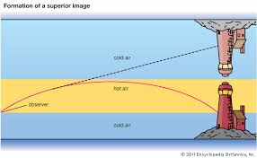
The Occurance of Mirage
Explain the occurrence of mirage
This
is the phenomenon inwhich an object appears to be at an incorrect
position due to the bending of light rays from the object.
is the phenomenon inwhich an object appears to be at an incorrect
position due to the bending of light rays from the object.
Mirages occur during hot days.
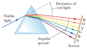
The Passage of Light through a Triangular Prism
Trace the passage of light through a triangular prism
Deviation of light in a prism is the changing in direction of the incident ray when it enters/hits a triangular glass prism.
Where i
is the angle of incidence
s is the angle of deviation
The minimum angle of deviation ( qm)
In order to determine the minimum angle deviating (Qm) then we must set triangular Glass prism as follows.
The Dispersion of White Light
Demonstrate the dispersion of white light
Dispersion of light is the splitting up of light beam (white light) into its seven components of colour by a prism.
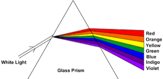
Spectrum is the patch or band of colours which comprise / constitute seven component of white light.
Pure section is the patch or band of colours in which the colours are clearly separated.
In order to produce pure spectrum then we must use two converging lenses (convex lenses).
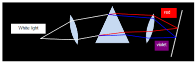
When colours of spectrum are combined, they form white light.
In order to combine colours of the spectrum, weneed two triangular glass prisms and one lens.
Impure spectrum:the band/patch of colours which overlap and are not seen clearly.
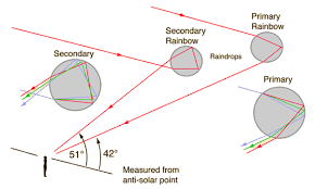
The rainbow:a
bow-shaped spectrum of seven colours of white light formed when white
light undergoes dispersion within the rain drops because water is denser
than air, so has a large refractive index.
bow-shaped spectrum of seven colours of white light formed when white
light undergoes dispersion within the rain drops because water is denser
than air, so has a large refractive index.
Activity 1
A rainbow can be demonstrated as follows:
Spray some water into the air in a direction opposite to that of the sun.
Look
at the water shower while you face away from the sun. You will see the
colour of the spectrum of white light in the falling drops of water. The
spectrum so formed hasthe shape like a bow. So it is called rainbow.
at the water shower while you face away from the sun. You will see the
colour of the spectrum of white light in the falling drops of water. The
spectrum so formed hasthe shape like a bow. So it is called rainbow.
There are two main types of rainbow:
- Primary rainbow
- Secondary rainbow
Primary rainbow
This
is formed when light undergoes one or single total internal reflection
in the water droplets. In this type of the rainbow the violet colour is
on the inside of the bow while the red colour is on the outside.
is formed when light undergoes one or single total internal reflection
in the water droplets. In this type of the rainbow the violet colour is
on the inside of the bow while the red colour is on the outside.
The Angles of Deviation and Minimum Deviation
Determine the angles of deviation and minimum deviation
Finding the refractive index (n) of glass by using the deviation of light in a prism:
Refracting angle of prism is A
Snell’s law
S in i/Sin r = N
Sin i= n sin r
Sin e’ = nsin i
From Geometry of figure
I = A- r
The total angle of deviation (s) is the angle between the direction orf the incident ray and the emergent ray.
Again from the Geometry Q is given by:
S= i+r’- A
When the deviation is a minimum (Sm) the passage of light through the prism will be symmetrical so:
I = r ‘and r = I’
This means that;
A + Smin = 2i = 2r’
Therefore;
Refractive index, n = Sin (A + Smin)/2
Sin (A/2)
Where
A = Apex angle ( angle of prism)
Smin – The angle of minimum deviation
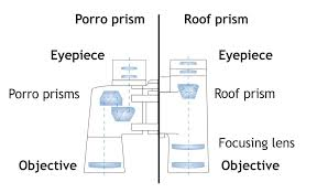
A Simple Prism Binocular
Construct a simple prism binocular
Simple prism binocular
Colours of Light
The Component of White Light
Explain the component of white light
There are two types of colour of light
- Primary colour of light
- Secondary colour of light
Primary colour of light
These are basic (fundamental ) Colour of light to which the eye is most sensitive.Primary Colour of light Include the following
- Red
- Green
- Blue
Secondary colours of light
These are colour of light obtained after mixing primary colours of light
Colour mixing by Addition
This is the process of combining primary colours of light without loss any colour to form secondary colours of light.
| Primary color | Secondary color | |
| Red + Blue | Magenta | |
| Red + Green | Yellow | |
| Blue + Green | Cyan |
Colours of White Light
Recombine colours of white light
When all white light ( Red , Blue and Green)Combineforms WHITE LIGHT.
Complementary colours of light: These are the colours which produce white light when combined.
- Red + Blue+ Green – White light
- Red + Cyan – White light
- Blue + Yellow – White light
- Green + Magenta – White light
The Appearances of Coloured Object under White Light
Explain the appearances of coloured object under white light
There are two types of coloured paints ( pigments) which Include the following
- Primary coloured pigment (paints)
- Secondary coloured pigment (paints)
Primary, Secondary and Complementary Colours of Light
Identify primary, secondary and complementary colours of light
Primary Coloured pigments
These are basic coloured pigments which form secondary coloured pigment when combined.
The primary coloured pigments include:Yellow, Cyan and Magenta
Secondary colour pigments
These
are coloured pigments which are formed when two primary colours
combine, whichis always accompanied with the removal of other colours.
are coloured pigments which are formed when two primary colours
combine, whichis always accompanied with the removal of other colours.
Difference between Additive and Subtractive Combination of Colours
Distinguish between additive and subtractive combination of colours
Colour Mixing by Substration
Is the process of mixing two primary coloured paints ( pigments) to form secondary colour white.
Example 3
- Magenta + Cyan
- Magenta = ( Blue) + ( Red)
- Cyan = (Blue) + (green)
The colour which is common to Blue will appear while red and green disappear.
Magenta + Cyan = Blue
Example 4
- Magenta + yellow
- Magenta = (Blue) + (Red)
- Yellow = (Green) + (Red)
The colour which is common to both red will appear while blue and green will disappear.
Hence
Magenta + Yellow = Red
Example 5
- Cyan + yellow
- Cyan = (Blue) + (Green)
- Yellow = (Red) + (Green)
The colour which is common to both green will appearwhile Blue and Red will disappear
Hence
Cyan + Yellow = Green
Refraction of Light by Lenses
Difference between Convex and Concave Lenses
Distinguish between convex and concave lenses
A lens is a transparent medium bounded by two surfaces of regular shape. There are two major categories of lenses which include:
The Terms Focal Length, Principle Focus, Principle Axis and Optical Centre as Applied to Lenses
Explain the terms focal length, principle focus, principle axis and optical centre as applied to lenses
Optical center is a geometric center of a lens. Center of curvature is the center of the sphere in which a lens is a part. Principal axis is an imaginary line which passes through the optical center of the lens at right angle to the lens. Principle focus is a point through which all rays traveling close and parallel to the principal axis pass through.
The Focal Length of a Lens
Determine practically the focal length of a lens
Focal
length is a distance between between optical centre and the principal
focus. It is important to note that the the principal focus is not the
halfway between the optical centre and the centre of curvature in lenses
as it is in mirrors. The plane through the principal focus which is at
right angles with the principal axis is called the focal plane.
Example 6
An object is 2 cm high and placed 24cm from a convex lens. An image formed 72 cm. find the focal length of the lens.
Solution
i/f = 1/u + 1/v
1/f =1/24 + 1/72
1/f = 4/72
f = 18cm.
The Immage Formed by a Lens
Locate the image formed by a lens
Rays diagrams are normally used toillustratesthe formation of images by lenses.
- A ray parallel to the principal axis passes through or appears to diverge from the principal focus after refraction.
- A ray of light passing through the principal focus of a lens is refracted parallel to the principal axis of the lens.
- A ray of light through the optical center of the lens continues throughundeviated(Not change direction)
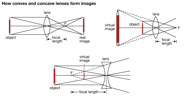
The position, Size and Nature of the Image formed by Lens
Determine the position, size and nature of the image formed by lens
The
nature, position and size of the image formed by a lens depends on the
position of the object in relation to the type of lens. For example in
converging lens when the object is between the lens and principal focus
the image will be formed at the same side as the object but further from
the lens. It is virtual, erect, and magnified. The image by concave
lens is erect, virtual and reduced.
Activity 2
- Take a convex lens. Find its approximate focal length in a way described in Activity 11.
- Draw
five parallel straight lines, using chalk, on a long Table such that
the distance between the successive lines is equal to the focal length
of the lens. - Place the lens on a lens stand. Place it on the central line such that the optical centre of the lens lies just over the line.
- The
two lines on either side of the lens correspond to F and 2F of the lens
respectively. Mark them with appropriate letters such as 2F1, F1, F2and 2F2, respectively. - Place a burning candle, far beyond 2F1to the left. Obtain a clear sharp image on a screen on the opposite side of the lens.
- Note down the nature, position and relative size of the image.
- Repeat this Activity by placing object just behind 2F1, between F1and 2F1at F1, between F1and O. Note down and tabulate your observations.
The
nature, position and relative size of the image formed by convex lens
for various positions of the object is summarized in the table below:
nature, position and relative size of the image formed by convex lens
for various positions of the object is summarized in the table below:
| Position of the object | Position of the image | Relative size of the image | Nature of the image |
|---|---|---|---|
| At infinity | At focus F2 | Highly diminished, point-sized | Real and inverted |
| Beyond 2F1 | Between F2and 2F2 | Diminished | Real and inverted |
| At 2F1 | At 2F2 | Same size | Real and inverted |
| Between F1and 2F1 | Beyond 2F2 | Enlarged | Real and inverted |
| At focus F1 | At infinity | Infinitely large or highly enlarged | Real and inverted |
| Between focus F1and optical centre O | On the same side of the lens as the object | Enlarged | Virtual and erect |
Activity 3
- Take a concave lens. Place it on a lens stand.
- Place a burning candle on one side of the lens.
- Look
through the lens from the other side and observe the image. Try to get
the image on a screen, if possible. If not, observe the image directly
through the lens. - Note down the nature, relative size and approximate position of the image.
- Move
the candle away from the lens. Note the change in the size of the
image. What happens to the size of the image when the candle is placed
too far away from the lens.
Nature, position and relative size of the image formed by a concave lens for various positions of the object
| Position of the object | Position of the image | Relative size of the image | Nature of the image |
|---|---|---|---|
| At infinity | At focus F1 | Highly diminished, point-sized | Virtual and erect |
| Between infinity and optical centre O of the lens | Between focus F1and optical centre O | Diminished | Virtual and erect |
The Magnification of the Lens Camera
Determine the magnification of the lens camera
As
we have a formula for spherical mirrors, we also have formula for
spherical lenses. This formula gives the relationship between object
distance (u), image-distance (ν) and the focal length (f ). The lens
formula is expressed as1/ν – 1/u = 1/f(8)
we have a formula for spherical mirrors, we also have formula for
spherical lenses. This formula gives the relationship between object
distance (u), image-distance (ν) and the focal length (f ). The lens
formula is expressed as1/ν – 1/u = 1/f(8)
The
lens formula given above is general and is valid in all situations for
any spherical lens. Take proper care of the signs of different
quantities, while putting numerical values for solving problems relating
to lenses.
lens formula given above is general and is valid in all situations for
any spherical lens. Take proper care of the signs of different
quantities, while putting numerical values for solving problems relating
to lenses.
The
magnification produced by a lens, similar to that for spherical
mirrors, is defined as the ratio of the height of the image and the
height of the object. It is represented by the letter m. If h is the
height of the object and h′ is the height of the image given by a lens,
then the magnification produced by the lens is given by,m = Height of
the Image / Height of the object = h’ / h(9)
Magnification
produced by a lens is also related to the object-distance u, and the
image-distance ν. This relationship is given byMagnification (m ) = h’ /
h = ν / u(10)
produced by a lens is also related to the object-distance u, and the
image-distance ν. This relationship is given byMagnification (m ) = h’ /
h = ν / u(10)
Example 7
A
concave lens has focal length of 15 cm. At what distance should the
object from the lens be placed so that it forms an image at 10 cm from
the lens? Also, find the magnification produced by the lens.
concave lens has focal length of 15 cm. At what distance should the
object from the lens be placed so that it forms an image at 10 cm from
the lens? Also, find the magnification produced by the lens.
Solution
A concave lens always forms a virtual, erect image on the same side of the object.
Image-distance v = –10 cm;
Focal length f = –15 cm;
Object-distance u = ?
Since, 1 /v – 1 / u = 1 / f
or, 1 / u = 1 / v – 1 / f
1 / u = 1 / -10 – 1 / (-15) = – 1 / 10 + 1 / 15
1 / u = (-3+2) / 30 = 1 / (-30)
or, u = – 30 cm.
Thus, the object-distance is 30 cm.
Magnification m = v/ u
m = -10 cm / -30 cm = 1 / 3 = +0.33
The positive sign shows that the image is erect and virtual. The image is one-third of the size of the object.
The Relationship between Focal Length (f) Object Distance (u) and Image Distance (v) as Applied to Lenses
Determine the relationship between focal length (f) object distance (u) and image distance (v) as applied to Lenses
The
lens equation is given as 1/f =1/u + 1/v , if sign convection is used
for u, v and f the equation applies to both converging and diverging
lenses for all cases of object and image.
lens equation is given as 1/f =1/u + 1/v , if sign convection is used
for u, v and f the equation applies to both converging and diverging
lenses for all cases of object and image.
Example 8
An object is placed 12 cm from converging lens of focal length 18 cm. Find the position of the image.
Solution
Since the lens is converging f = +18 cm. 1/v = 1/18 -1/12, v = -36.
The image is virtual.